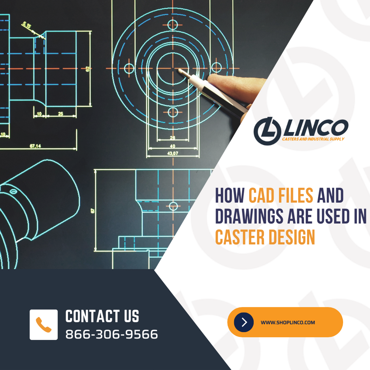
When it comes to designing casters or caster wheels, precision and accuracy are highly important. This is where Computer-Aided Design (CAD) files and drawings step in as powerful tools. Today, we’ll explore how CAD files and drawings are used in the designing process for casters, simplifying complex concepts to help you understand their significance in a concise and straightforward manner.
What Are CAD Files and Drawings?
CAD refers to the use of computer software to create detailed and accurate 2D or 3D models of objects.
CAD files serve as digital representations of these models, containing comprehensive information about dimensions, materials, and other specifications. They contain precise information about the dimensions, geometry, and features of an object or part. CAD files allow designers to create, modify, and visualize designs in a digital environment, providing a detailed blueprint for manufacturing.
Conversely, drawings are visual representations of CAD models, often produced on paper or in digital formats. These drawings provide views of the object or part from different angles, showing dimensions, annotations, and other relevant information.
CAD drawings serve as a means of communication between designers and other stakeholders, ensuring a clear understanding of the design intent. They are often used for documentation, manufacturing, and assembly purposes.
Using CAD Files and Drawings in Caster Design
CAD files and drawings are indispensable tools in the design and development of casters and caster wheels. From conceptualization to manufacturing, these digital assets enable engineers and designers to visualize, refine, and validate their designs efficiently.
Conceptualizing the Design
Before any physical prototype is built, designers use CAD software to create a digital representation of the caster. CAD files enable the visualization and exploration of design ideas, allowing for quick modifications and iterations.
By using various tools and features, designers can accurately define the dimensions, shapes, and features of the caster. This helps ensure everything meets your desired specifications for the project.
Precise Measurements and Tolerances
A significant advantage of CAD files and drawings is their ability to provide precise dimensional information. They enable designers to specify precise measurements and tolerances for the caster wheels.
Engineers input accurate measurements and constraints into CAD software, ensuring the seamless integration of caster components. Detailed drawings minimize errors during the manufacturing phase. In doing so, the design can be optimized for functionality and performance.
This level of detail ensures that the caster will fit properly within the intended application and function as expected.
Analysis and Simulation
CAD software offers powerful analysis and simulation capabilities that aid in the caster CAD design process. Designers can simulate the performance of the caster or caster wheel under various conditions, such as different loads or operating environments.
By analyzing stress distribution, friction, or other critical factors, it is easier to identify potential design flaws and rectify them early on, saving you precious time and resources.
Integration and Compatibility
In many cases, casters need to be integrated into larger systems or equipment. CAD files allow designers to ensure compatibility and proper integration by accurately representing the mounting points, attachment mechanisms, and other crucial details.
This ensures that the caster can be seamlessly incorporated into the overall design without any conflicts or compromises.
Communication and Collaborative Design
CAD files and drawings foster effective collaboration among design team members. They are a common language between designers, engineers, manufacturers, and other stakeholders involved in the production process. Sharing digital models allows engineers to gather feedback and suggestions from colleagues and stakeholders.
This collaborative approach promotes efficient communication, reduces errors, and ultimately leads to an improved final design. CAD files also make it easier for different teams to understand and provide feedback. Everyone can review, discuss, and collaborate on the caster CAD design, leading to better outcomes and reducing the chances of misunderstandings.
Manufacturing and Prototyping
CAD files and drawings serve as vital references for manufacturing and prototyping once the caster design is finalized.
Detailed drawings provide manufacturers with all the necessary specifications and dimensions required to create accurate physical prototypes or generate production-ready parts using CNC machines. Referring to these files ensures that casters are produced according to the design intent.
Get Quality Caster CAD Design Assistance With LINCO
Leveraging the power of CAD technology, the caster industry can deliver robust, precise, and high-performing products that meet the diverse needs of various applications. From conceptualizing the design to analyzing its performance and facilitating collaboration, CAD files and drawings ensure designers can create casters that excel in functionality, durability, and overall performance.
LINCO provides a wide range of CAD drawings and CAD files in various formats to help you and your business with your project. Whether you need DWG, DXF, PDF, or other file formats — and whether you require 2D or 3D files — our team can provide you with the solutions you seek.
More importantly, LINCO offers a variety of customization options to ensure you get a caster solution that meets your project or industry’s unique requirements.
Call us at 866-306-9566 today or visit our contact page to leave a message.

